UT3: Modeling tips
This tutorial will go over the basics on modeling for UT3, and the theory behind why models need to be built in a certain way.
To understand how we need to model for UT3 (or any engine for that matter) we need to understand how lighting works in the engine, and see which settings we will use. Understanding these things will allow us to save polygons, or save visual quality. First let’s break down the different types of lighting an engine can use.
Dynamic lighting:
Pros - Shadows are very accurate based on what geometry casts shadows and where the shadows fall.
- Dynamic objects cast moving shadows, adding to the believability of the game.
Cons - Dynamic lighting is very expensive in comparison to the other lighting methods.
Vertex Shadows:
Pros - Since every piece of geometry contains vertex coordinates, the shadow values are in a sense there, just turned off, because of this, the engine can calculate the shadows based on vertex coordinates VERY easily and at low cost.
Cons - Compared to the other lighting methods, this is the most inaccurate calculations, and the visuals may suffer because of it.
- The shadows are static, meaning there is no movement at all.
Lightmap Shadows:
Pros - You can control the visual quality of your shadows, how sharp they are or how soft.
- The shadows are MUCH more accurate than vertex shadows.
- Shadows can fall on a large polygon plane with variation, as where other lighting methods (vertex lighting in this example) cannot, since it requires geometry to control the fall off of the shadow.
Cons - Lightmap shadows require a baked texture to indicate the complexity of the shadow detail, because of this, the more detailed you want your shadow, the large the texture, the more memory is used, the longer it takes to load and the less memory the engine had to handle every thing. Be careful to only use this option where it is needed. Light mapping everything will make it look great, but lower the overall performance.
Let’s break down the good method for UT3 vs. the bad method. Remember, every engine handles things differently, so the image you see below might work great (especially if you have dynamic lighting); you save polygons, and maintain the visual quality. However, with UT3, you cannot model things this way, especially if you are using the default vertex lighting. This is why.
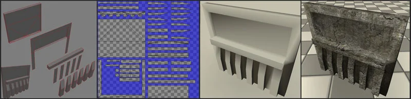
Bad modeling method for UT3:
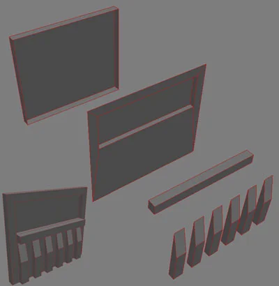
In this model, the two large pieces are only separated to illustrate how it is fully modeled.
The window sill is not welded into the geometry itself, it is simply placed on top of the large polygon surface.
The 6 extrusions at the base of the model are also simply placed on top of the polygon surface.
Over all, the poly count for this model is 49, (98 tris)
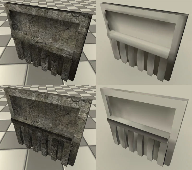
The result of this modeling method in the UT3 engine with the default vertex lighting looks like this.
Good modeling method for UT3:
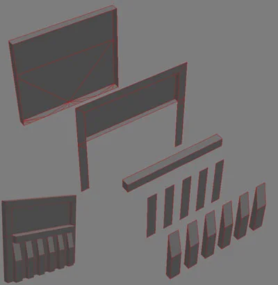
In this model, every piece that you see extracted, when put back together will have no seams or un-seen edges. Everything in this model is merged, welded and one solid piece with no wasted space.
Over all, the poly count for this model is 84 (142 tris), nearly 50% more than the previous model.
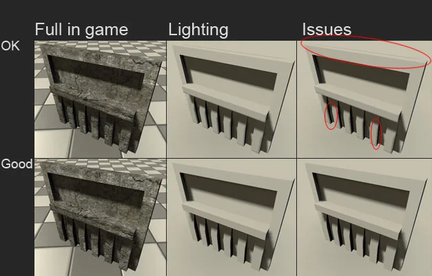
Look down at the images below.
The top model is the vertex lit version with the incorrect modeling method.
The bottom model is the same lighting but with the correct modeling method.
The image to the right is simply a shadow preview option inside UT3 editor to visualise how the shadows fall on the objects in the scene.
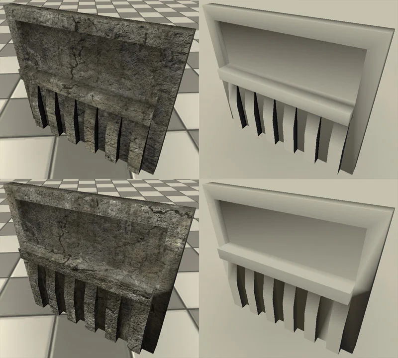
Note: The textures are off just because changing the model required some re-uving.
The first image has a solid gradient the entire way across the back bottom face, also notice how the insides of each extrusion is extremely dark when in the shaded view.
The bottom image has more unity in the shaded areas. Even when the lighting may be a bit off on the far right compared to the first image, in the lit mode, effects are hidden in the textures. Also notice the window ledge is more clear compared to the first image. There are pros and cons for each modeling method, but on a whole, the one with the better results is the bottom image (correct modeling method). In the right lighting, you can get individual shadows for each extrusion instead of having an even gradient the whole way through.
Below are 3 models; the good model and bad model as shown above in the break down images, and another model that is 'OK'. It will work, but the shadow results are different. I will show the examples and explain why.
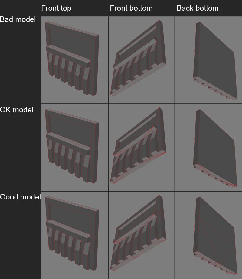
The only difference between the 'OK' model and 'Good' model is that there is a split in geometry half way up. I put this detail in to help support the surrounding geometry. Since on the front face, there is a lot of detail the entire way up (most vertical detail is in the middle) I placed a split in geometry to support that detail on the edges. It does not add too much geometry, and the fall off shadow effect is more accurate to what would happen in the real world.
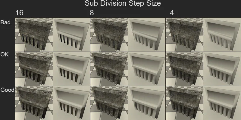
In regards to the 'Sub Division Step Size', it is covered under the 'vertex shadow tweaking' tutorial. In a nut shell, it helps control the fade off of vertex shadows.
As you can see, the correct modeling method (Good) has all the shadows in the middle to the bottom, as where the 'OK' model stretches the detail across the entire piece of geometry. Also notice on 'sub d' #8, the shadow bleeds over to the extruded geometry in the front, where as the 'Good' model at 'sub d' #8 maintains the detail of the shadow.
Laying out your UV map 2 for light baking in max:
First I will show you two identical models with different UV layout, and the results you get when done incorrectly.

This is the lightmap settings I used for both the renders, and yet you will see a big difference between them.
The Top model has bleeding of shadows and everything is soft with little definition.
The second model is slightly blurry compared to the first model, but there are no strange artefacts in the render itself. All the edges of each face are sharp.
The reason for this is a mixture of the size of the baked shadow texture on your mesh, and the space between your UV pieces in your original 3d package (in this example, I will be showing the UV's through the UT3 editor). First I will illustrate the method with an example.
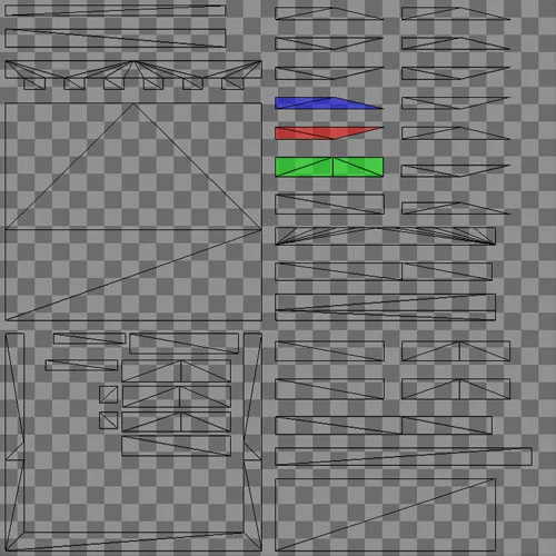
If you are baking out a shadow map in UT3 with the setting of 32, that is a 32X32 texture. If you then over lay a UV texture onto a checker board at that density, this is what you will see. To make things more obvious, I enlarged the scale a bit.
Each square you see in this image represents a pixel if the UVs are laid out at the resolution of 32.
The dark lines you see are the UV's of our geometry inside UT3.
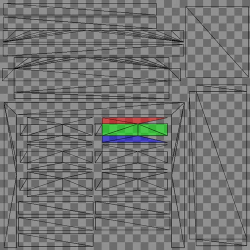
For example purposes, I highlighted one of the extrusions with red, green and blue to show the separated smoothing groups.
You can see that if each square represents a pixel, then at the transition point from one face to another, the pixels overlap. This is very important when UV'ing your lightmap channel.
In real life, the hard edge is where the transition takes place for shadows, but if your UV's are too close together, or if hard edged geometry has its UV's welded at these points, you will get bleeding of shadows, especially at low resolution renders of the shadow map.
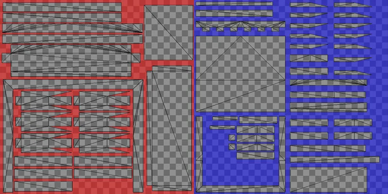
As you look at the new UV lay out, each piece that is not a part of the same smoothing group (there is a hard edge along the geometry) is split in the UV’s. The overall size of the UV space is smaller, which is why the shadow map is more blurry, however it greatly lowers the change of bleeding.
This is a comparison between the old UV layout, and the new UV. The red and blue represents the negative space around the UV's. On the left is the old UV layout, and on the right is the new UV layout.
A good 'quick and easy' way to lay out your 'Lightmap' Uv channel is to break up the UV's how you want, and inside the UV editor in max use the 'Flatten' function. Inside this tool, there is an option to offset each UV from one another. Some tweaking may be required after the use of this tool, but it is a VERY handy function to get you 95% of the way there.
You might think that by simply setting the lightmap resolution higher, this will fix the problem, however issues still come up, even if they it is set to 256.
As you can see, even with a much higher lighting resolution, there are still issues. There is a dark line along the top, the pegs at the base shows bleeding, and the transition from the side to the front of the extrusions is soft (because the uv's are welded).
Don't forget, the higher the resolution of the shadow map, the more resources it uses up. Use it sparingly.
I hope this little tutorial has helped you out. i thank you for your time.