Complete asset creation process

This tutorial will go through the entire process of creating a simple asset, and what to look out for. I will cover the references, modeling, UV'ing, texturing and normal map creating as well as some theory.
The first step for any asset creating is to find out how this asset will be used in the level, and the level of detail it will require.
This process includes the poly count, whether or not it will be animated or destructible, the level of detail required for the texture and how it will be rendered in the game engine (vertex lighting, light map / shadow map lighting, dynamic lighting. This step will affect how the model will be modeled) for this example, I will assume this model will be lit dynamically which will allow us to keep the poly count low.
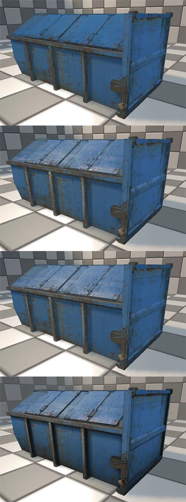
The next step is to figure out the dimensions of your model. First step is to acquire references which will be used both for the modeling and texturing of the asset. Also, lining up these models to figure out the scale of the asset.
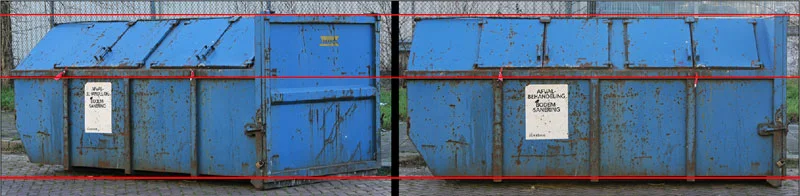
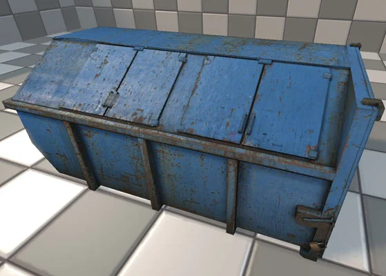
With this image, we can roughly estimate the shape in 3d of how this model will look like. A little research will be required to find out the original size of this particular dumpster, as well as how units in your 3d package will copy over to your games engine. For example, 96 “Generic” units in max is the height of a 6 foot human being in UT3 (16 units to a foot). If this dumpster is roughly 6 feet tall, then make it 96 “Generic” units in max.
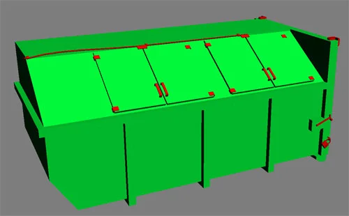
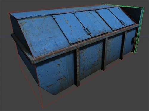
The dumpster in the image above is measured “relative to itself”, Height: 1, Length: 1, Width: 2.2.
Since the height of the dumpster will be 6 feet (96 units), the length will also be the same, but the width will be 211.2 units.
Since I want this model to be able to snap easily to different assets in the level, I will have to round up the measurements to make things easier. Unreal can snap easily to 1, 2, 4, 8 and 16 units. The increments go higher, but unless you're making something large like a building, these should be fine. If I round up the width to 212, it can be divided by 4 evenly.
When rounding out the measurement numbers, you want to keep the units as large as possible without compromising the overall scale of the asset too much.
This “blocked out” version of the model is currently 121 polygons, fairly low at its current state, but will soon go up in count as we add detail. For right now, this is simply the 'base' model.
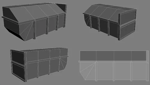
The next step is to add the doors, panels, hinges and pipes (details). Keep in mind that the doors on this model will not be opening, so the door model should be built directly out of the current geometry, placing a polygon plane over top will simply waste texture space further down the road.


At this stage, the poly count is 850. The basic shape of the dumpster has stayed the same with a few minor tweaks, but details have been added.
Doors, Metal holders, Hinges and Locks make up for the extra 739 polygons. This might seem like a lot for such small details, but depending on how close you get to the model and how detailed you want the textures to be, all of these details can add a lot of character to an otherwise dull model.
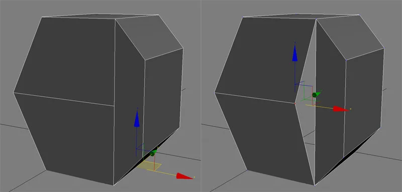
First off, you will need to make sure there are no open edges on the mesh. If you have polygons with a gap, even if it looks like it is closed, there is a chance it is not, and this can cause some serious issues later on down the road.
Most large objects in games now a days 'occlude' the objects behind it, which means that if an object is hidden, it is not rendered. The problem with games is that the negative side of faces are not rendered by default, so if there is a gap in your mesh and the object behind it is visible in any way, it will render out the entire mesh. This is not a huge problem for smaller assets, but when you're dealing with a building hidden behind another building, then you will be drastically affecting performance.
This image shows the gap in a very simple model. Even though models inside max, Maya and other 3d modeling programs do support n-sided faces (more than 4 edges to a polygon), the left image gives the illusion that that's what's going on, where in fact it is not.
This model can cause some serious issues when occluding objects behind it as well as 'in game flickering'. There is a tutorial I covered about this which I strong recommend reading if you have not already.
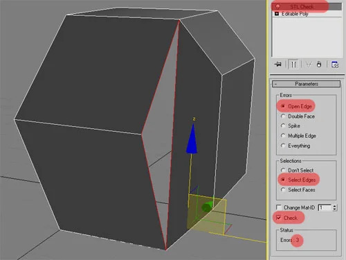
In 3D Max, there is a function located under the Modifier List called 'STL Check'. With this tool you can locate any double faces, multi edges or open edges on your model.
You can also choose to view the edge or the face of this problem.
In order for these to show up, you must click the “Check” option.
Secondly, you need to work with your smooth groups. This can easily be mis-understood by artists.
If you noticed, most, if not all of the surfaces on this model are hard edges. Dumpsters in the real world have relatively smoothed out corners, and that is completely possible to do with this model, but a lot of issues can come up because of it.
For those of you who have a good grasp of smooth groups, feel free to skip this section.
Smooth groups do not have an (in-between) value set. They are either on, or off. By 'on or off' I am referring to the edges of the model, not the faces. Smooth groups smooth out the model between at least 2 faces to give the illusion of it being smooth, or in contrast, it hardens a single face to make it stand out from the other polygons. The following simple models will illustrate this.
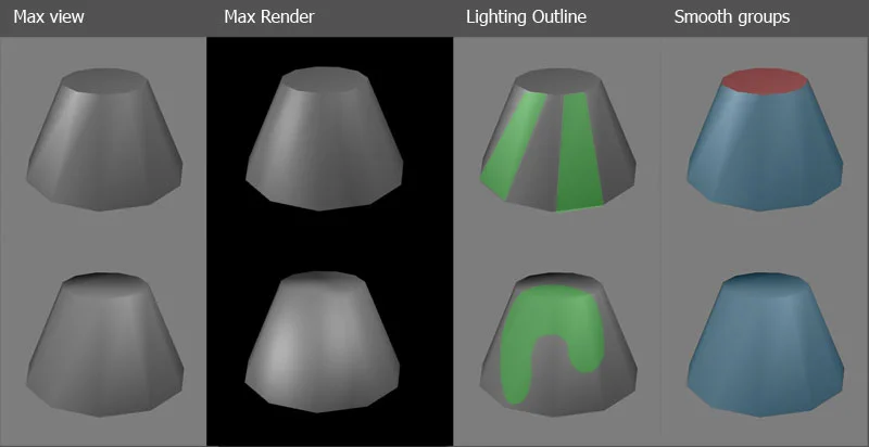
The top row has 2 smooth groups, the bottom has only one.
The first and second columns are the max models, and their renders. The third is the highlight of the lights themselves, and the fourth is the colour separation of the smooth groups.
As you can see above, the light highlights change when the smooth groups are altered. This plays hand in hand with normal maps if you choose to “correct” this visual issue. If you desire the entire model to be one smooth group and be smooth, that is fine, but a problem arises. Look at the farthest left side of the image above. The top model looks fine, and for the most part, so does the bottom; however there are a few things that need to be clarified. The bottom model should NOT have a dark, nearly black area on the top. The reason for this is because the model is trying to smooth out from the lit side and the un-lit side, and this causes problems such as this to arise. If you create a high poly model and back out a normal map, this WILL correct the issue.
When you create any model, always keep in mind what parts will be seen from which angle, and how detailed they need to be. How big the textures will be and the amount of detail desired.
There are ways to create rounded corners on sharp objects without getting this un-desirable artefact, but the quality of this depends greatly on the model as well as the area of the texture the UV's take up. The texture size itself is not as important as the amount of pixels the faces will use in the model itself.
This is the basics of smooth groups and hi-poly models. This was borrowed from
http://wiki.polycount.net/Normal_Map
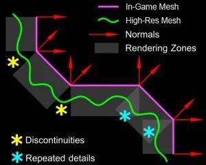
If you choose to create a high poly version of a low poly model, keep this diagram in mind. Depending on where you create your details, and where you want things to be, different smooth groups will give different results. This also applies to models that you are taking over. Do not assume you know how it was created or modeled. Study the model, as well as the normal maps you have.
For the sake of this model (the dumpster) I am giving each side their own separate smooth group to allow for overlapping UV's, which increases the detail applied to the model when the texture faze is started.
When I work on the smooth groups of any model, I set the smooth 'value' anywhere from 45 to 85 (not 90, because if my model is slightly off, it will create one smooth group where I want 2). I Then manually select faces and start to make smooth groups where needed. Do note that any series of connected faces that are completely flat should always share the same smooth group to make sure there are no un-wanted hard edges.
In the model of the dumpster, there are a total of 7 smooth groups. On a side note, do not make too many smooth groups where they are not needed. If you have a cube, to make it perfectly black, only 3 smooth groups are needed, not 6 (one for each side). If 2 faces never touch, they can share the same smooth group, also faces can have 2 smooth groups assigned to it, allowing for blending of one face into another.
Thirdly you will need a high-poly model to smooth out all the corners where needed, But these details will be applied on only a few selected areas (hinges, pipes and other small areas). The normal map created out of this high poly model (depending on the texture size you are using, the size of the texture, and the level of detail you want to add in) can really 'pixolate' your model in the long run, so use it wisely. The way I will be creating this model is through a single 1024X1024 texture. This might be a little high depending on how detailed you want it to be, so I will create it in 2048X2048 and down size it later on to show the difference between a 2048X2048 1024X1024 and 512X512 for the normal map. The level of detail is entirely up to you, but as a rule, games should share a 'texture size' rule based on how detailed you want your texture to be based on its size.
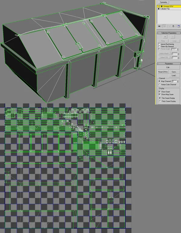
After everything is set up, the next step would be to UV your model. This depends on a few things, and some were discussed prior to this section.
Will the UV be used for Light Map textures in the engine?
Will there be an ambient occlusion baked into the model.
Will the front and back be different, or will they share the same uv space.
Will there be a high poly model made based on the low poly which will be used to create a normal map for the entire thing.
What sides of this asset will be visible.
How many UV channels are allowed for this model?
All of these things play directly with how the asset will have its UV's laid out, how you will create the diffuse, normal map or ambient occlusions, and how the shaders will be laid out...
1. If the UV's will be used for a light map, and you are only allowed a single UV channel, then none of the UV's can over lap. If you are allowed 2 UV's, (this will increase the rendering time slightly) then the same rule applies, but on the second UV channel instead of the first. (The second UV channel usually holds the light map UV's. This is not always the case. If you need the second UV for a different texture for some reason, the light map can take the third, or even fourth UV channel.) Also, all the UV's must be within the 0 to 1 UV space if used for light maps.
2. If there is an ambient occlusion, it is possible to have overlapping UV's, but it can be VERY tricky at times to bake out a good ambient occlusion and remove any artefacts you do not want. Not every model needs this option. Also, the UV's also need to be in the 0 to 1 space when you bake out the ambient occlusion pass. Because the light map also needs to be in the 0 to 1 space, and have absolutely no overlapping, quite often it is a good idea to use the light map UV channel for your ambient occlusion pass if you are overlapping your original UV's. If you are not overlapping your original UV's, and every piece of geometry has its own coordinates, then it is much more convenient and cheaper to have the diffuse, ambient occlusion and light map all sharing the same UV space.
(Depending on the game engine, this option can be a different texture all together at a lower res, and can be placed over top of the original diffuse all together to add that 'ambient occlusion' feel. This will increase the memory size when dealing with textures, but you can share a texture color for something like a spec map. If you create a spec map that is simply black and white, then you only need one of the red, green or blue channels. If the RED channel is your spec map, then your GREEN channel can be your specular power, and your BLUE channel can be your ambient occlusions. This will increase rendering slightly, but increase the overall look of your model, as well as save texture space.)
I will be showing this in a “RGB spec” tutorial.
3. If the front and back of the model are the same, then they can share similar UV's. Depending on the model, this can greatly increase your texture detail since the back side will not take up any more UV space, but share it with another part of the object itself.
4. If a high poly model is used to bake out a normal map, the UV's need to be within the 0 to 1 UV space, and nothing can over lap when the baking takes place, however, UV's can be moved later on. If you have overlapping UV's, the normal map will double its value in that spot.
5. If you are creating a model where the bottom is never visible (no explosions to move the model, no animation or scripted scenes) it is still best to have the geometry there, but the uv's can either share other uv space, or be scaled WAY down in size. Doing this will allow for more detail in the texture to be used on other parts of the model.
6. If multiple UV's are allowed (try not to go over 2 or at the max 3) then a second channel can be used for normal maps, ambient occlusions or Light maps. This does increase rendering, so try to use it only when it is needed most.
Now to lay out the UV's for your model. I will create 2 different UV's, one for the diffuse and specular texture (over lapping) and a second for light maps and an ambient occlusion.
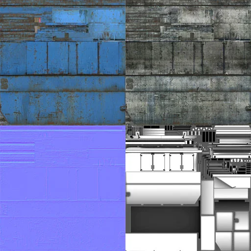
In this image, the green represents geometry that is flat and does not require a (corrective) normal map, as where the red areas do.
I say 'Corrective' normal map because normal maps have different functions. If you create a model and slap a normal map created from Photoshop on it, all it does is add detail to the overall model, making it look bumpy, but a 'Corrective' normal map corrects how the normals of the geometry appear and how they pick up spec maps. This is almost always created out of a high poly model which is baked on to a low poly model. (This is all covered in the normal map tutorial)
A rule for creating normal maps is that if you want smooth specular highlights, if your geometry bends a lot, then chances are you will need to create a high poly to create a normal map and smooth it out. Keep in mind that this directly depends on the size of the model, and the detail put into it.
If you are creating a small model, or if your texture is small itself, creating a normal map with lots of detail can be lost or extremely distorted. If you want to create something like a car paint or shiny metal that has a reflection, a pixolated normal map (due to size) can cause a lot of strange 'reflections' on your model and blobby normal map details.
Let’s create the UV's. Personally I create the light map first if I will be overlaying UV's later on for the diffuse. The reason for this is so everything is neatly laid out and evenly scaled, so placing setting up the UV's for the diffuse, spec and normal map can go rather smoothly.
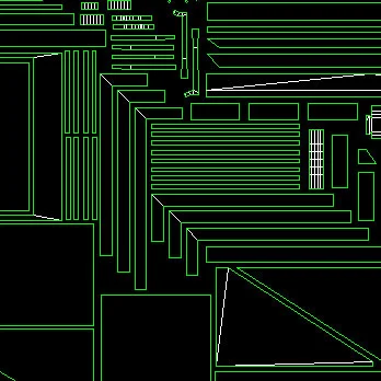
This is the result of the Light map UV space.
A rule for creating normal maps is that if you want smooth specular highlights, if your geometry bends a lot, then chances are you will need to create a high poly to create a normal map and smooth it out. Keep in mind that this directly depends on the size of the model, and the detail put into it.
If you are creating a small model, or if your texture is small itself, creating a normal map with lots of detail can be lost or extremely distorted. If you want to create something like a car paint or shiny metal that has a reflection, a pixolated normal map (due to size) can cause a lot of strange 'reflections' on your model and blobby normal map details.
Let’s create the UV's. Personally I create the light map first if I will be overlaying UV's later on for the diffuse. The reason for this is so everything is neatly laid out and evenly scaled, so placing setting up the UV's for the diffuse, spec and normal map can go rather smoothly.
This is the result of the Light map UV space.
When creating the textures for any model, I always start out with the diffuse map first. The reason for this is so I can use the contrast and details of the diffuse to add details on the specular channel and the normal map. Also, if you separate the diffuse in layers, you can mix and match whichever details you want, making it easier to achieve the look inside the games engine. It saves time in the long run.
I will not go through the details of creating the diffuse because that should be straight forward, as well as specs and normal maps, however, I will talk about some details in those textures starting with the diffuse.
Diffuse:
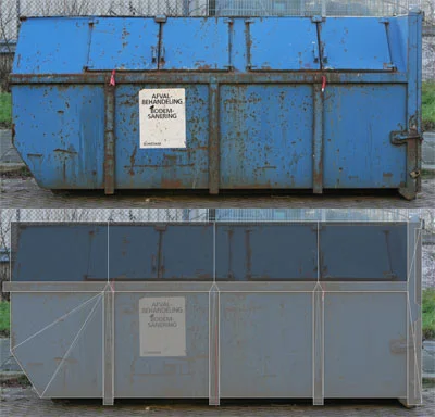
The dumpster's diffuse was taken directly from the reference images, however I did have to copy over a different reference image and tweak the color, the reason for this is because a part of the top, one side, back and bottom are not visible at all. Details such as the lock are not important because the details would be so small, any reference image would be useless due to the small UV space it takes up. When I copied over the front diffuse onto the texture, I painted over the metal extruding pipes. The reason for this is so I can use the entire bottom part of the texture elsewhere on the model and not worry about dark protruding metal slabs; those details were elsewhere on the model.
Specular:
Most people use a black and white specular channel, and although this works at times, I would not recommend it. Specular maps are GREAT for giving metal that true metallic look, and if all you get is a white (or light color) highlight, it can contribute to the lowering realism of your assets creation. Color is our friend, and should be used wisely. In the Unreal Engine, you can even use the diffuse at times as a specular map if the colors fit, or are close enough.
Normal Maps:
The normal map is quite often the trickiest texture to create. This can cause your model to look even more real, or extremely fake. Experiment with when and where to use the details to optimise your model creation. At times you will have to re-uv a few areas to find out where you need detail in the normal map, and where you can share the same details to optimise your assets details.
For this model, the asset was created with overlapping UV's. The extruding metal pieces (around the top and the extruding rim) are all sharing the top left UV area which allows for a lot of saved UV space. Thinking about these details ahead can save you time and details.
Look at your model and break it into pieces based on what type of texture they are. In this case, there was the body, trim, sides, top (doors) and details. The areas that are the same can at times share the same uv space. The front, top (very top, not the doors) back and bottom can all share similar UV's. The two sides can share UV's, and lastly the trim can as well since most of it has similar rust all around.
This top image is the basic diffuse on the model. By itself, no normal map detail or specular highlights will be visible, and as a result looks very flat, however, depending on where your asset will be used, or what it is, eg. Small stones, you can have only the diffuse. This causes the engine to process this asset VERY fast in comparison.
This image has the diffuse and specular channel applied. Right away you can see a big improvement with the visual improvements with having a spec map. A spec map in games unites the object with the world, allowing it to play with the lighting around the scene. If you do not have a spec channel, the only thing that gives your model shape is the shadows.
This image has a normal map applied to it. The details in this image are hard to see, but in some areas it is noticeable. The images below will illustrate this much better. Normal maps are an amazing way to add very fine details to your model. Scratches, Dents and bevelled corners can be added without the use of polygons, providing a much more visually interesting asset.
This image has an ambient occlusion texture baked from 3ds Max and tweaked in Photoshop applied to it. If you look above at the textures, you will notice that the ambient occlusion does not match the other 3 textures; This is because it is taking advantage of the 0-1, non overlapping UV's of channel 2 which is used for the light map. This can add a lot of realism in your model, but increases the render time. New versions of 'UT3/Gears of war' have an in game ambient occlusion system implemented, removing the need to manually bake out this texture.

Depending on how the lighting is set up, different angles will give you different specular highlights. The specular parameters of the model are what give the normal maps their detail. Without spec, the normal maps are not as noticeable.

This image is a close up of the front side of the dumpster. The red box illustrates what the images below are (this is for scale purposes so you can see how detailed things should be) The dumpster you see now is as close as most people will get in the game, so if it looks good from this distance, then it is fine.
If you look closely, there is not a huge difference between the normal map of 2048 and the one of 1024, however when you go down to 512, you really do notice the difference. Keep in mind that there is a 'details' normal map placed over top of the original normal map, so if we take this out, this is the result we get.
Without detail normal map applied
With detail normal map applied

Diffuse: 1024x1024
Spec: : 1024x1024
Normal: 2048x2048
Diffuse: 1024x1024
Spec: : 1024x1024
Normal: 1024x1024
Diffuse: 1024x1024
Spec: : 1024x1024
Normal: 512x512
With the images above, you can see that adding a detailed normal map to your model at times can hide blurry textures.
* Important
When you re-scale your images to find out what the best proportions are for the model, make sure to sharpen your texture AFTER you scale it down. Remember that you can get rid of detail by scaling down, but you cannot grab detail out of thin air by scaling up, so always create your textures AT, or ABOVE the detail that you will require, and then scale it down. IF you scale down, make sure you sharpen it, but only sharpen ONCE. Over use of the sharpen tool gives very dotty, multi colour artefacts which are not ideal.
The top image has the scaled down textures WITHOUT a sharpen filter applied.
The bottom image has the scaled down textures WITH the sharpen filter applied.
Also note that this image has the following texture measurements in the final version.
Diffuse: 1024X1024
Normal Map: 1024X1024
Specular: 512X512
Ambient Occlusion: 256X256
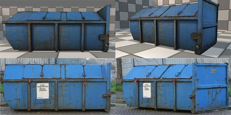
UT3 has a different camera focal length than real cameras which gives this 'fish eye' appearance when close to certain assets, that's why these images do not match up exactly.
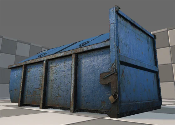
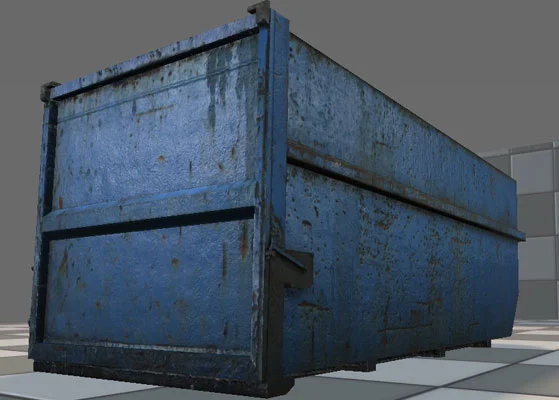
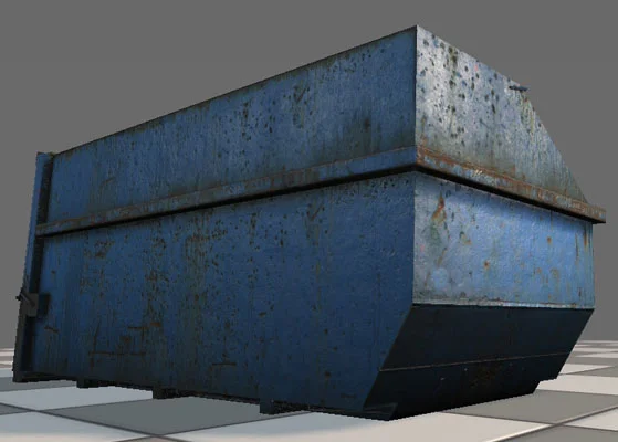
The image above is the 'in-game model' on top and the 'original' reference below.
The good thing about how the texture was laid out with this model is that it can be used on different containers as well, an oil drum for instance.
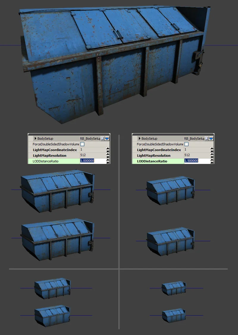
Finally we will need to create collision for the model. This method changes from engine to engine, and many times you can create this either in your 3d modeling software, or in the games engine itself. Both have their ups and downs. In this case, we will be covering the UT3 method of creating collision geometry.
Firstly, you need to understand what the engine can work with. Usually there is a wiki online you can refer to. For UT3, their collision wiki is located here. http://udn.epicgames.com/Three/CollisionReference.html#Collision_Models
The most basic collision types are cube, cylinder and sphere. Out of these 3, the cube has the least amount of verts making it the cheapest collision object. This will be used the most out of any collision.
To view your collision in UT3, double click on your model in UT3 and on the top left, select the 'Show Collision' button.
Creating collision inside UT3 gives the following results on this model.
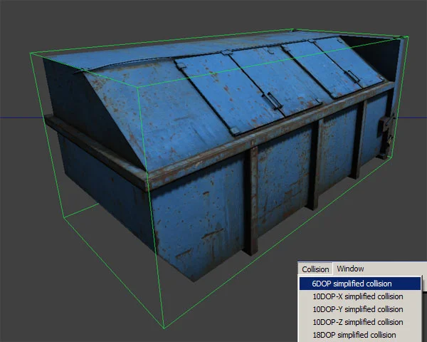

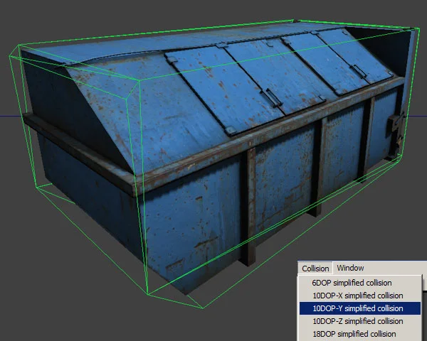

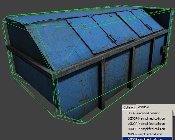
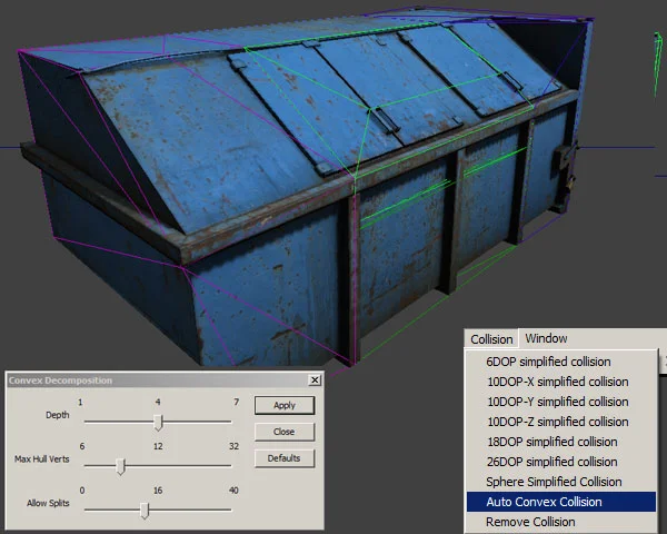
As you can see, with the exception of '6DOP simplified collision', every other engine generated collision has a lot of geometry to calculate and will greatly slow down your game play. You may be wondering about the last one 'Auto Convex Collision'. At times you can get a pretty good collision with this function, but it is not ideal. Collision boxes can never be concave, they must always be convex, which is why the last model has multi colour collision boxes. Each color represents a separate collision box, removing any 'concave' geometry.
What we want is a blend between the first one '6DOP simplifies collision' and the 'Auto Convex Collision', but to do this, we will need to create them ourselves inside max.
This bit of information was taken from the following web site. http://udn.epicgames.com/Three/CollisionReference.html#Collision_Models
You can create collision model in a 3D Modeling Program (3D Studio Max or Maya).
Simply create boxes, spheres or convex objects and place them around your mesh appropriately. These shapes will be converted to collision models in Unreal if they are named properly.
The naming convention (which is case sensitive) is as follows:
UBX Box Primitive
USP Sphere Primitive
UCX Convex Mesh Primitive
Boxes are created with the Box objects type in MAX or with the Cube polygonal primitive in Maya. You can't move the vertices around or deform it in any way to make it something other than a rectangular prism, or else it won't work.
Spheres are created with the Sphere object type. The sphere does not need to have many segments (8 is a good number) at all because it is converted into a true sphere for collision. Like boxes, you shouldn't move the individual vertices around.
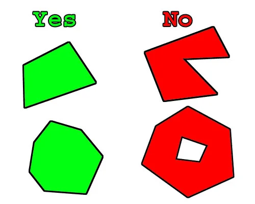
Convex objects can be any completely closed convex 3D shape. For example, a box can also be a convex object. The diagram below illustrates what is convex and what is not:
Note that currently spheres are only used for rigid-body collision and Unreal's zero-extent traces (e.g. weapons), not non-zero extent traces (e.g. Player movement). Also, spheres and boxes do not work if the static mesh is non-uniformly scaled. In general you probably want to create UCX primitives.
Once your collision objects are set up you can export both the graphics and collision mesh in the same .ASE file. When you import the .ASE file into UnrealEd it should find the collision mesh, remove it from the graphic, and turn it into the collision model.
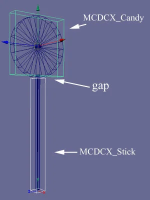
Note: In the case of an object whose collision is defined by multiple convex hulls, results are best when the hulls do not intersect with one another. For example, if the collision for a lollipop were defined by two convex hulls, one for the candy and one for the stick, a gap should be left between the two as in the following illustration:
Breaking up a non-convex mesh into convex primitives is a complex operation, and can give unpredictable results. Another approach is to break the collision model into convex pieces yourself in MAX or Maya.
To do this, you use the bOneConvexPerUCXObject option on the Static Mesh importer. With this option checked, each UCX_ object in the file will be turned into exactly one primitive. If the object is non-convex, it will just have a convex hull wrapped around it to make it convex. This gives you a lot of control, and is a good idea for complex meshes.
I strongly recommend you read that page listed above. It will advise you with all your collision needs.
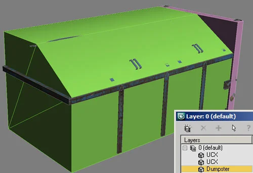
The pink and green boxes are the collision pieces, both with the name 'UCX' (case sensitive).
When you export the geometry, simply save it as a regular .ase file. When you import it into unreal, do what you normally do, and in the 'static mesh editor', you will see this.
The image to the left is the in-game geometry with custom collision. The red and green boxes are the custom collisions imported into the game. This is all you need to do for it to work.
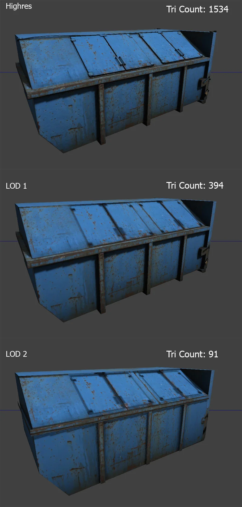
The next step is to create an LOD model for this asset. Most of the details we added after the boxed in model will be removed for this as well as changing the material the engine uses. At a distance, you can quite often get away with having no normal map, that plus the removal of the 'details normal map' and possibly even the spec channel will greatly improve the engines speed. Let’s get started.
To import your LOD models into unreal, open up the 'Static Mesh Editor' and select 'Mesh/Import Mesh LOD'. Inside max, export the LOD models just like you did the original, but only the model, no collision geometry. Create 2 different files for both LOD models. You will be asked which LOD the imported file should be placed in when you import the files. Link up the material to the model, and you're done. (A new LOD version of the material should be created for the LOD's which exclude normal maps)
These models show the difference between a “LOD Distance Ratio” of 1, vs. a ratio of 1.5.
The two models relatively equal in size show the transition point. The top image of each is the higher res, as where the lower image of each is the lower res. The value of 1.5 causes the transition point to be placed between the two transition points with the setting of 1.
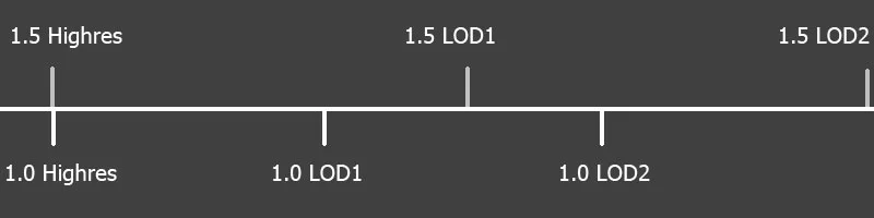
This value determines how far away the next LOD model will kick in. Not every model should kick in at the same distance. Changing this value has both its ups and its downs. The further away the model transitions from the high res to one of the LOD's, the less likely you will be seeing any 'popping' of models, however it does increase the distance that the engine calculates the highres version, increasing the processing power required.
I hope this little tutorial has helpd you out. i thank you for your time.